Model Broker for Diagrams
Increase your engineering productivity, reduce time and costs!
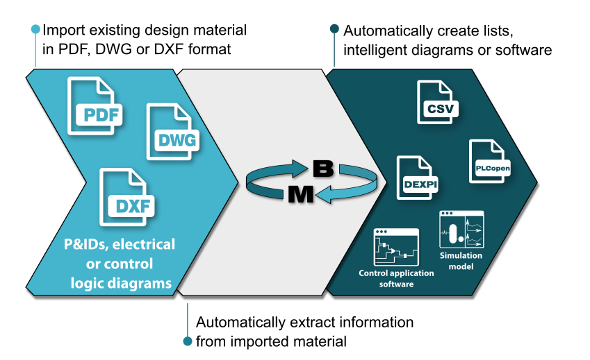
Model Broker for Diagrams is an application for automatic recognition and extraction of information from engineering diagrams in PDF, DXF or DWG formats.
Model Broker for Logic Diagrams helps automating the engineering effort required to create different engineering assets from existing engineering drawings. Automatic data extraction also reduces possible errors caused by manual data extraction and interpretation.

Symbol recognition

Target formats
Vectorized diagrams support
Model Broker for Diagrams supports engineering drawings in vectorized PDF, DXF and DWG formats as source material. Vectorized drawings differ from raster images as they are composed of well-structured paths, while raster images are bitmaps of pixels. Most of the CAD tools utilized in industry for drawing logic diagrams support vectorized PDF format. Raster image support is currently under development.
Are you interested in knowing if your design material is supported by Model Broker for Diagrams? Do not hesitate to contact us for more information!
Translation based on adaptive rules
Model Broker for Diagrams can recognize symbols, their connections and text in the source diagram. It then automatically extracts this information and maps into the target format. Automatic translation into the target format is based on editable symbol recognition and mapping rules that can be edited according to the source material for improving the results.
Editing these rules is easy and it is required only once before the actual data extraction is carried out. Initial configuration of the translation rules can be based on pre-existing configuration presets. However, these rules can be further customized to adapt to your design material.
Multiple target formats supported
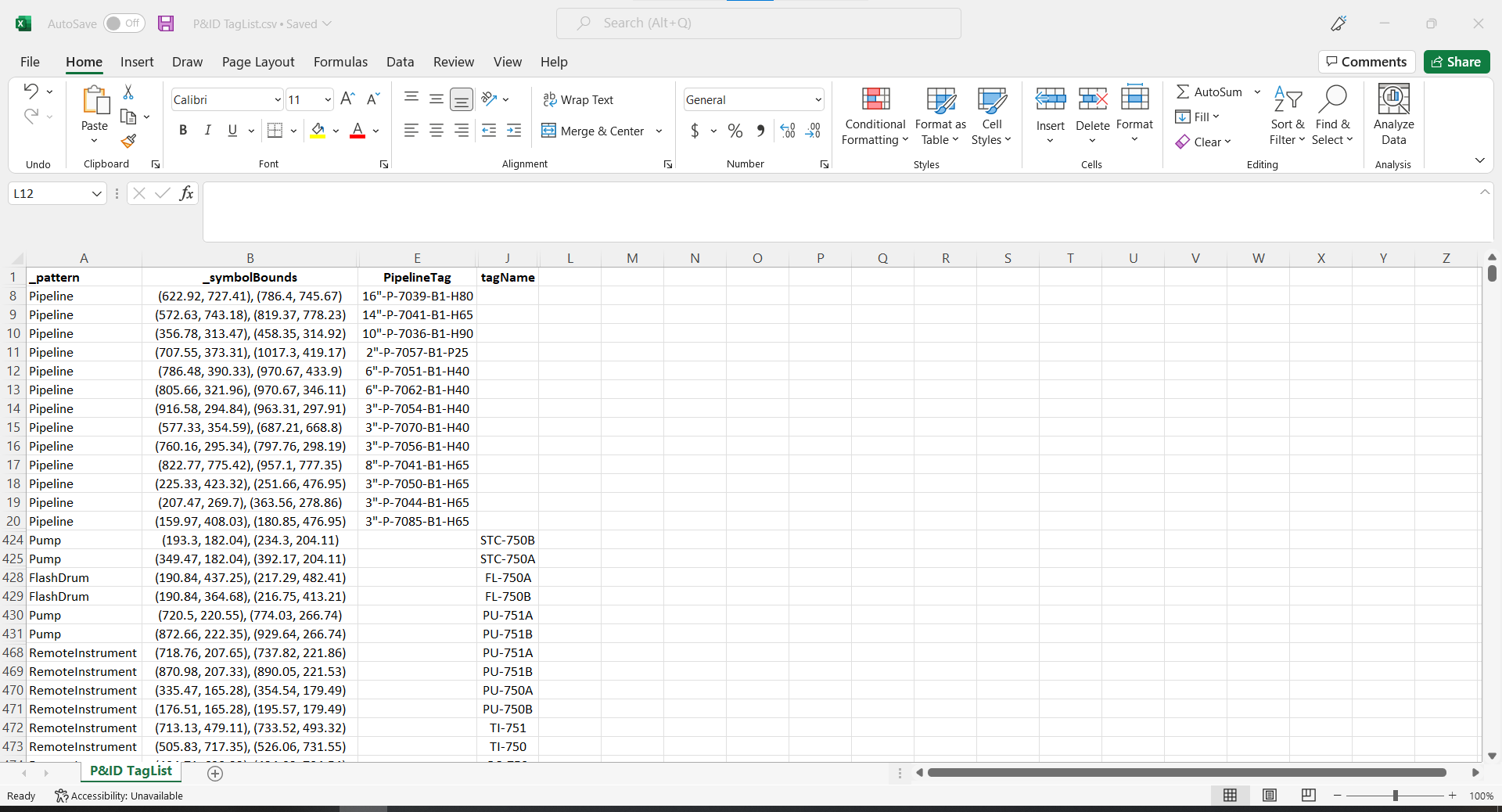
P&IDs’ information can be extracted to create lists of equipment, lists of pipelines or lists of instruments. P&IDs can also be converted into DEXPI format to create intelligent diagrams or to integrate with other systems supporting this industrial standard.
Extracted information in electrical and logic diagrams can be used to create list of automation I/Os or lists of control loops. This information can also be used to create PLCopen XML files (IEC 61131) for automatically creating PLC software or DCSs control applications. Logic diagrams can also be used to create Apros control application models.
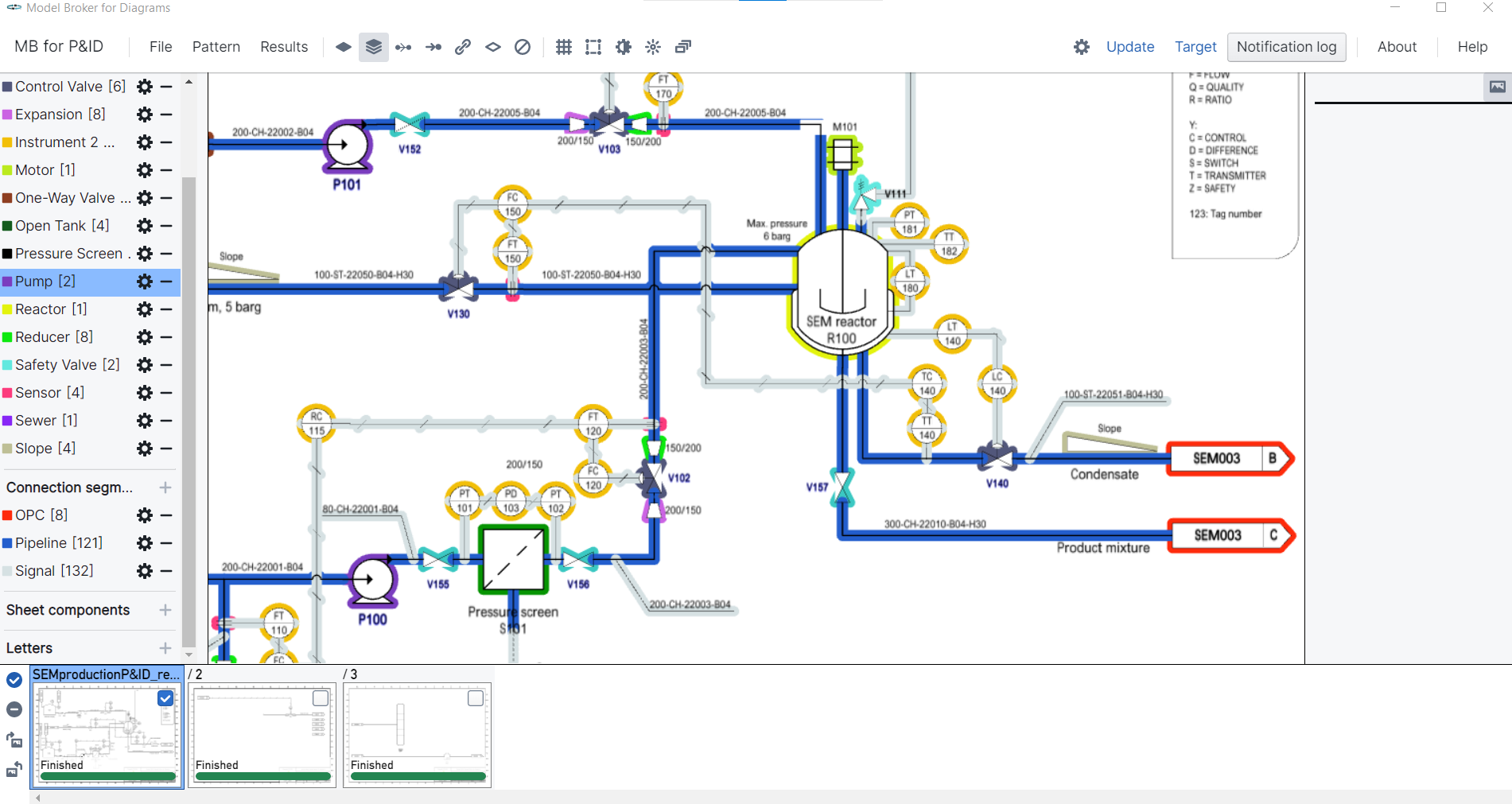
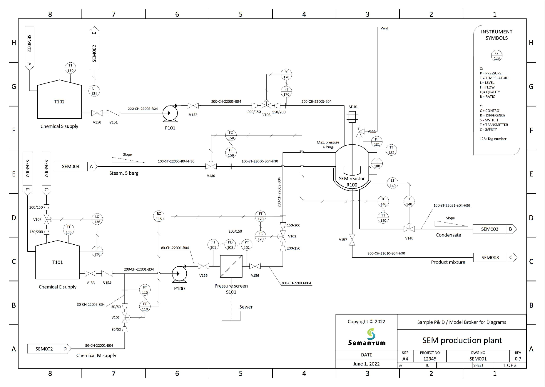
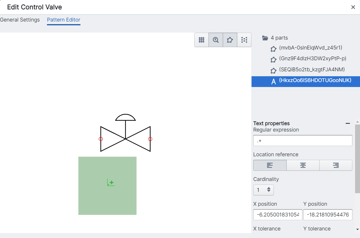
Screenshots
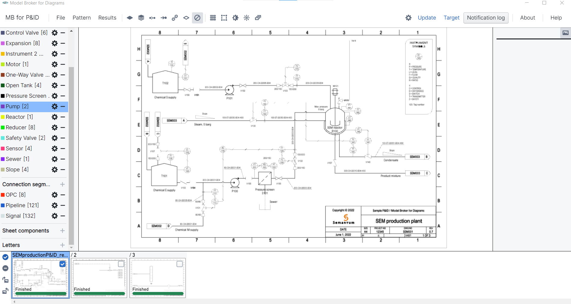
Diagram visualization
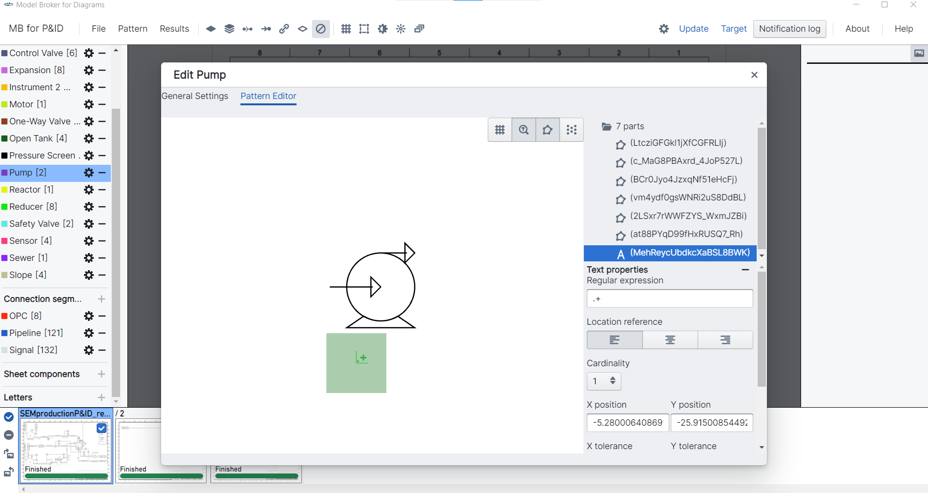
Symbol configuration
Symbol recognition results